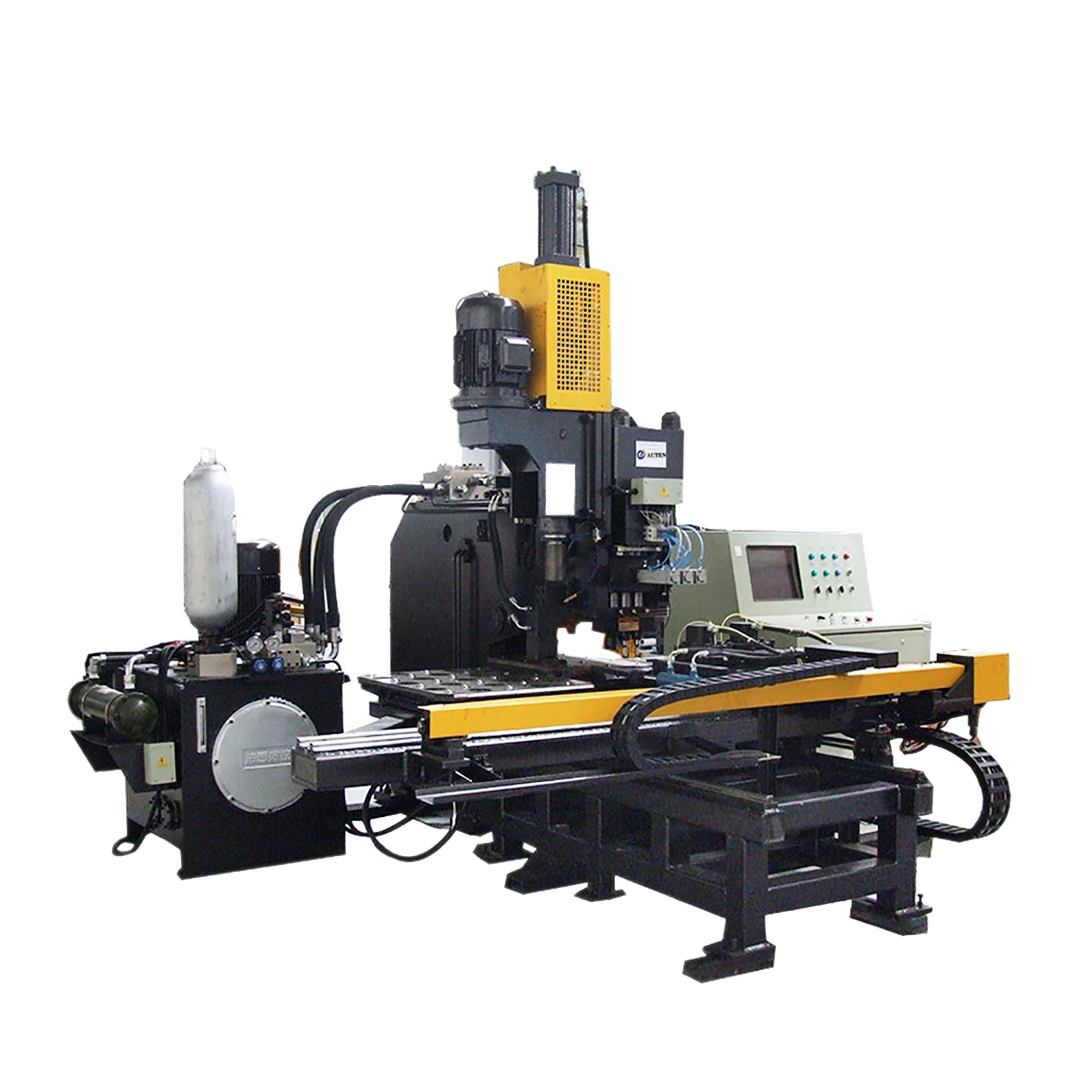
This machine is mainly used in petroleum machinery industry, for milling the trapezia slot on petroleum screen pipes, the slot’s width is CNC controlled, multiple tools in the machine can work simultaneously, which makes the manufacturing efficiency very high.
CNC Screen Pipe Milling Cutting Machine for Petroleum Industry
This machine is mainly used in petroleum machinery industry, for milling the trapezia slot on petroleum screen pipes, the slot’s width is CNC controlled, multiple tools in the machine can work simultaneously, which makes the manufacturing efficiency very high. The automatic manufacture can be fulfilled once the machining parameters are input into the control panel, it’s convenient and simple to do the programming and operation. This machine is a kind of flexible manufacture system, it’s good for batch production with multiple specification. It can replace laser cutting or other technology cutting method for petroleum screen pipes, its’ feature is: high work efficiency with low cost.
Machine’s structure and configuration:
This machine is mainly composed of the base, the column, the cross beam, the headstock, the supporting saddle, the cooling system, the pneumatic system and the electric system, etc.
1. The base adopts integrated fabricated type of structure, processed with ageing treatment, the work accuracy is very stable. The base is the installation basic of the whole machine, the column and other components are all installed on it, its’ good welding structure and rigidity can effectively assure the whole machine’s work stability.
2. This machine totally has three columns for supporting the cross beam. There is one roller linear guide way installed on each column, the guide way is used for guiding the headstock’s up and down movement. This roller linear guide way has simple structure and it’s convenient to do the maintenance, its’ aseismatic performance and holding accuracy performance both are better than common guide ways.
3. The cross beam is installed over the column, there are two sets of servo motor and ball screw, which are used for driving the headstock’s up and down movement, the two servo motors drive the two sides simultaneously through ball screw after the reducer’s speed reduction, the feed back respond is good with high positioning accuracy. Double sides simultaneous driving assures the headstock’s parallel movement and the perpendicularity of the headstock during its’ up and down movement. There is holding cylinder installed on the crossbeam, which holds tightly the work piece in the process of machining, assures the work piece’s stability and reduces the vibration.
4. The headstock is made from cast iron, the transmission system adopts full gears transmission, which assures the transmission efficiency. There are 22 main spindles in the headstock with one machining tool on every spindle. Every two adjacent spindles’ rotating direction is reverse, which can counteract the longitudinal cutting resistance in the process of machining. The headstock’s power is input by two frequency conversion motors after gears’ transmission, it’s convenient to adjust the spindle’s rpm by using frequency conversion motor. There is one cooling nozzle installed on every spindle, to cool the tools while machining, sufficient cooling can effectively improve the tools’ work lifetime.
5.The supporting saddle is used for supporting the work piece, the V type structure assures the stability of supporting. It can be adjusted if the work piece’s diameter varies a lot, which can assure enough work capacity. The supporting saddle has the swing angle function, the angel fluctuation is 6°, which facilitates the machining when the work piece has narrow upside and wide lower side. Accordingly, there is assistant supporting saddle both in front of the main machine and in rear of it, which facilitates feeding the work piece in the longitudinal direction.
6. The cooling system uses centrifugal pump to supply water, for cooling the tools, the coolant can be used in recycle, sufficient cooling can effectively improve the tool’s work lifetime.
7. The pneumatic system works for holding the work piece and the angle swing fluctuation of the supporting saddle.
8. The machine’s CNC system adopts PLC and upper computer, the operation is fulfilled through touching screen, which facilitates the program’s setting, saving, displaying and communication. On the operating interface there are man-machine conversation, error compensation, automatic warning functions and the function of previewing the machining process before running and recheck, the operation is very convenient.
9. The machine’s roller guide way, precise ball screw, servo motor, servo driver and PLC all are key components, all of them take world famous brand name manufacturers’ products, so the machine’s reliability is very high, and its’ performance can be compared with high-end world famous machines, with very few trouble and high work efficiency.
Item | Parameter | |
Work range | Steel pipe’s diameter | φ70-φ220mm |
Headstock | Spindle quantity | 22 |
Spindle jumpiness | ≤0.1mm | |
Spindle centerline’s distance | 152.4mm | |
Milling tool’s Max. diameter | φ75mm | |
Tool width | 0.25-5mm | |
Spindle rpm | 100—1200r/min | |
Spindle motor power | 2×11kW | |
Headstock’s up and down movement distance | 200mm | |
Servo motor power/torque of Z axis | 2X1kW | |
Maximum moving speed | 8m/min | |
Pneumatic system | System pressure | >0.5Mpa |
Cooling system | Cooling way | Outside cooling |
Cooling pump capacity | 200L/min | |
Cooling pump motor power | 2×0.45kW | |
Electric system | CNC system | PLC |
CNC axis | 2 | |
Motor total power | About 25kW | |
Overall size | L×W×H | About 5.4×2.8×1.9m |
Weight | About 15 tons |

