
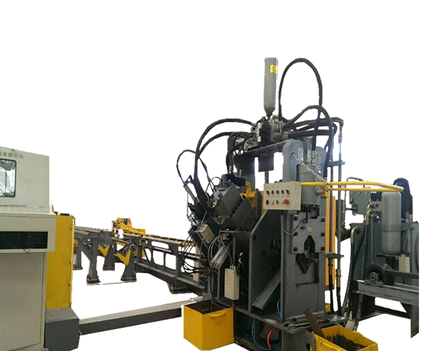
CNC Angle Punching, Marking and Shearing Machine
CNC Angle Processing Machine
Angle size: 40x40x3~200x200x20mm
Max. Hole size: 26mm
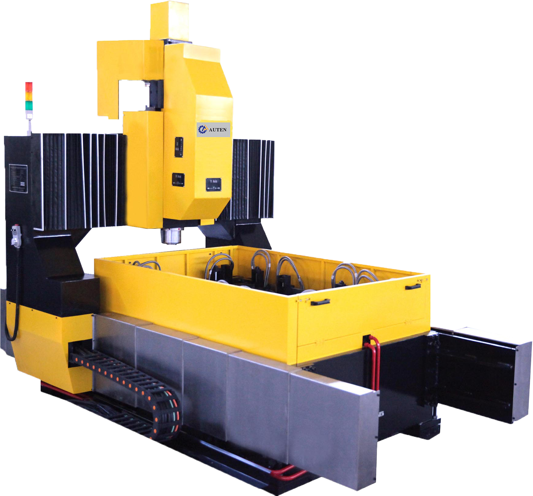
High Speed CNC Plate Drilling Machine
It is mainly used in steel structure drilling in construction, bridge, tower etc., and can be use din pipe and plate of boiler, petro line, baffle plate and round flange.
LEARN MORE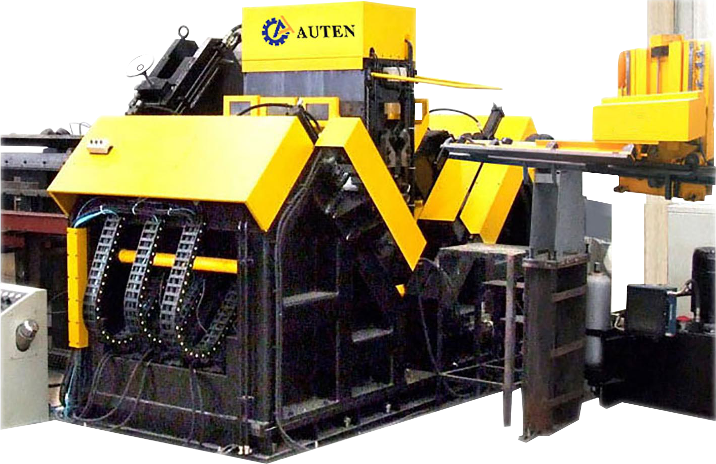
High Speed CNC Angle Drilling and Marking Machine Line
Used for angle steel drilling & marking mainly in the field of angle steel tower industry.
LEARN MORE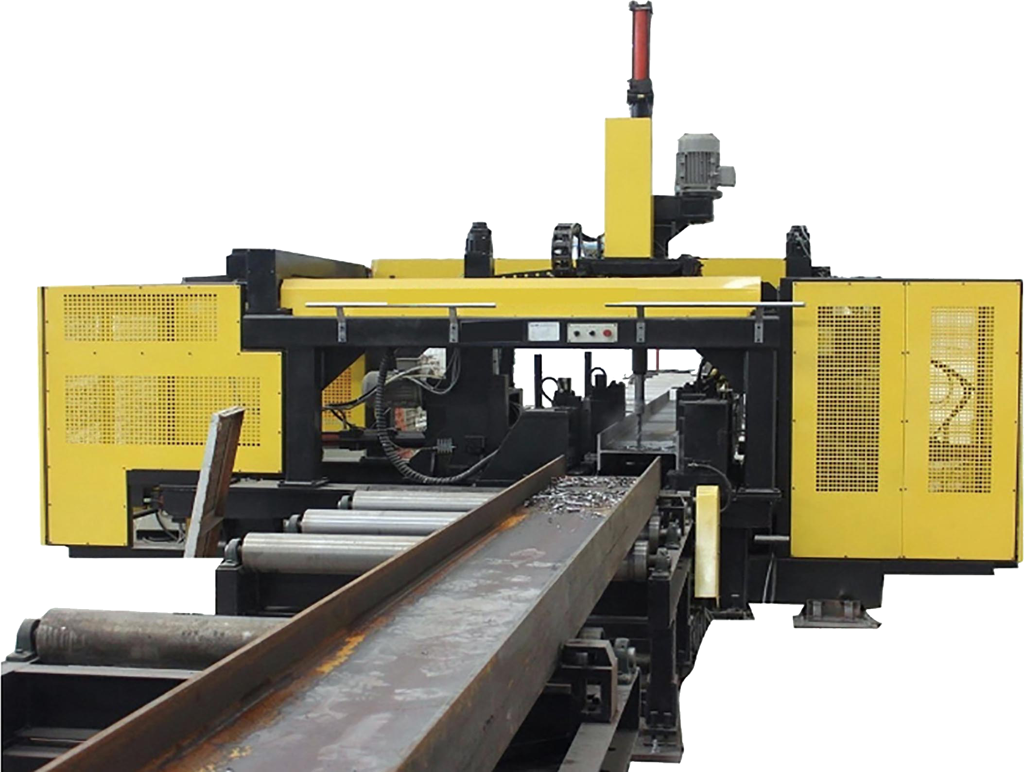
CNC H Beam Drilling Machine Line
Used for the drilling processing of H-shape steel, box beam and channel steel of steel structure, bridge, three dimensional garage and petrol platform. It is designed for medium size steel fabricators desiring to increase profitability and throughput (tons-per-month) in today’s extremely competitive market.
LEARN MORE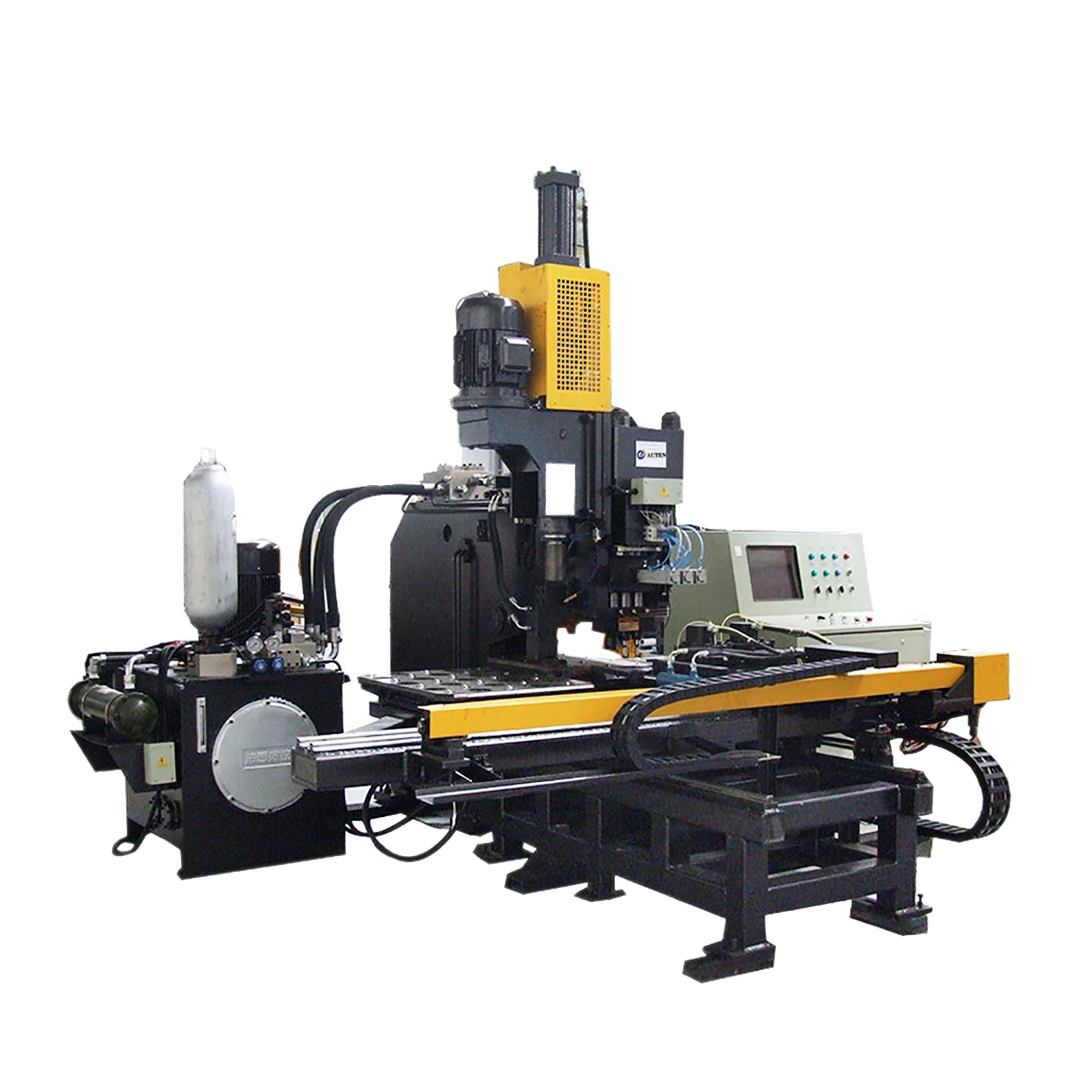
CNC Plate Punching, Marking and Drilling Machine
Used for punching, drilling and marking joint plates in the field of iron tower. It is also used to punching, drilling and marking metal plate in other industry field.
LEARN MOREIt is a complete production line for automobile flat longitudinal beam punching. According to the punching needs of various car frames at home and abroad, and integrates various product advantages. developed products. This production line can perfectly meet the flexible processing requirements of various frame longitudinal beams, and has the characteristics of stability and high efficiency.


